Hartley Hut, Canning Half- Tide Dock, Liverpool Waterfront: Updated investigations into the Hut’s condition and a phased repair schedule with detailed specifications and methodology.
Contents- Introduction, Brief History and Description of the Hartley Hut, Issues, methodologies and schedules of work for: Re-pointing of the stonework to the external walls; Removal of existing mastic to upper roof sections, removal of existing cement repairs to previous lifting points, re-pointing, removal of existing mastic pointing to lower outer slabs and re-pointing work; Advice on potential tie works to the roof slabs to counter the movement and cracking; Removal of vegetation and greening to external stonework faces; Removal of rust staining and later steel from the stonework; Removal of existing paint and salts to internal walls; and Proposal to open the existing fireplace, windowsills, & and floor screed
Introduction
Harrison Stringfellow and their client, National Museums Liverpool, requested that M Womersleys carry out additional inspections and testing and prepare some specifications and method statements to repair and refurbish the Hartley watchman's hut at the waterfront. This report will provide mortar analysis results from samples taken of the original building mortars and offer an appropriate repointing specification; Set out the condition of the granite slabs on the roof and suggest remedial works; Will provide a suitable specification for a herbicide; Provide advice on dealing with the rusting historic fixings; Will advise on a suitable alternative to the current mastic to the underside of the external cornice; and Provide a detailed specification removing paints and salts from internal walls.
A Brief History and Description
Liverpool’s docks dominated global trade by the early 19th century. When it opened in 1846, Albert Dock was of a superior design; its warehouses were fireproof and secure, and the speed with which ships were unloaded and turned around was cut in half. The Octagonal watchman's hut on the North side of the pierhead, shown on the title page, was formerly listed with two other huts, shown in photograph 1 below. It was built circa. 1844 and designed by Jesse Hartley as part of the broader Albert Dock complex. It is constructed of granite rubble, defined by well-cut and dressed ashlar blocks, that form window and door surrounds, the battered base and roof slabs now finished with a stone bulb finial. 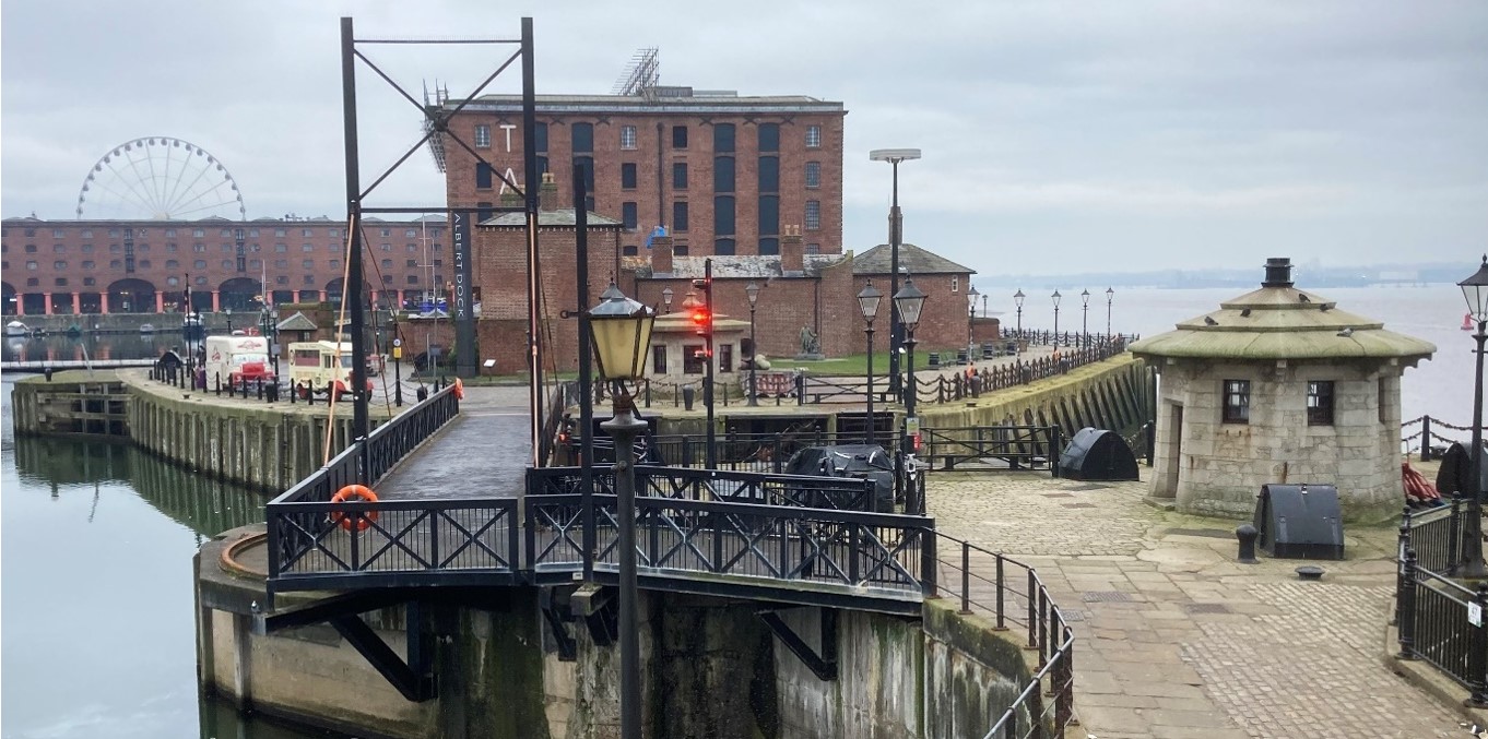
Photo 1: A view from the survey Hartley Hut, looking south towards two similar huts and the Albert Dock. (Jan. 2023)
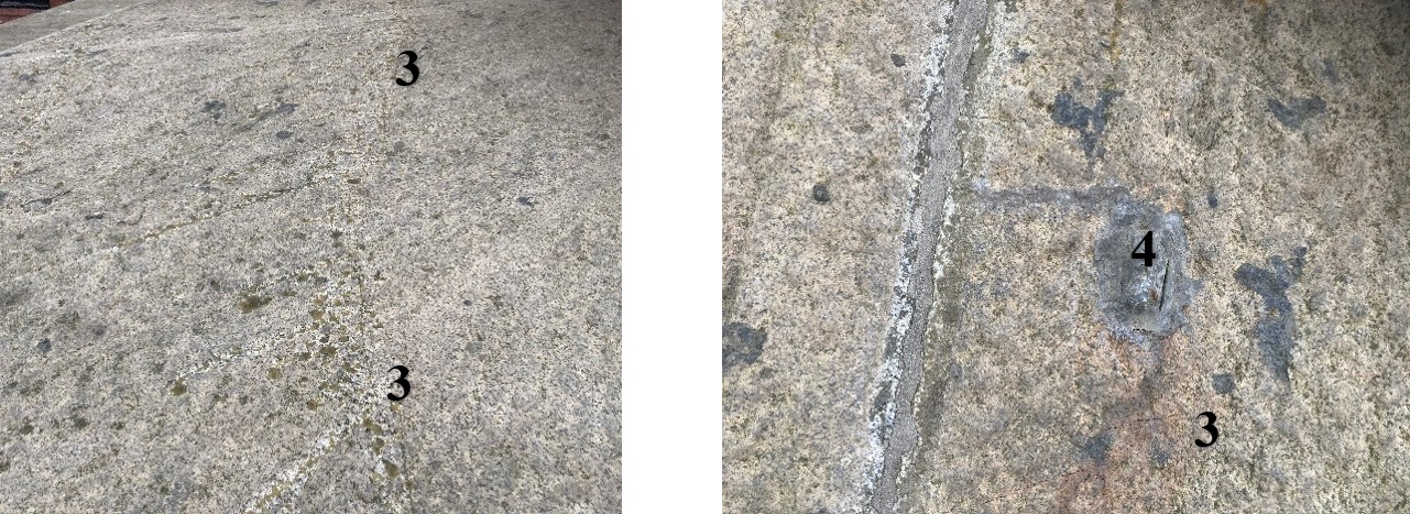
Re-pointing of the stonework to the external walls.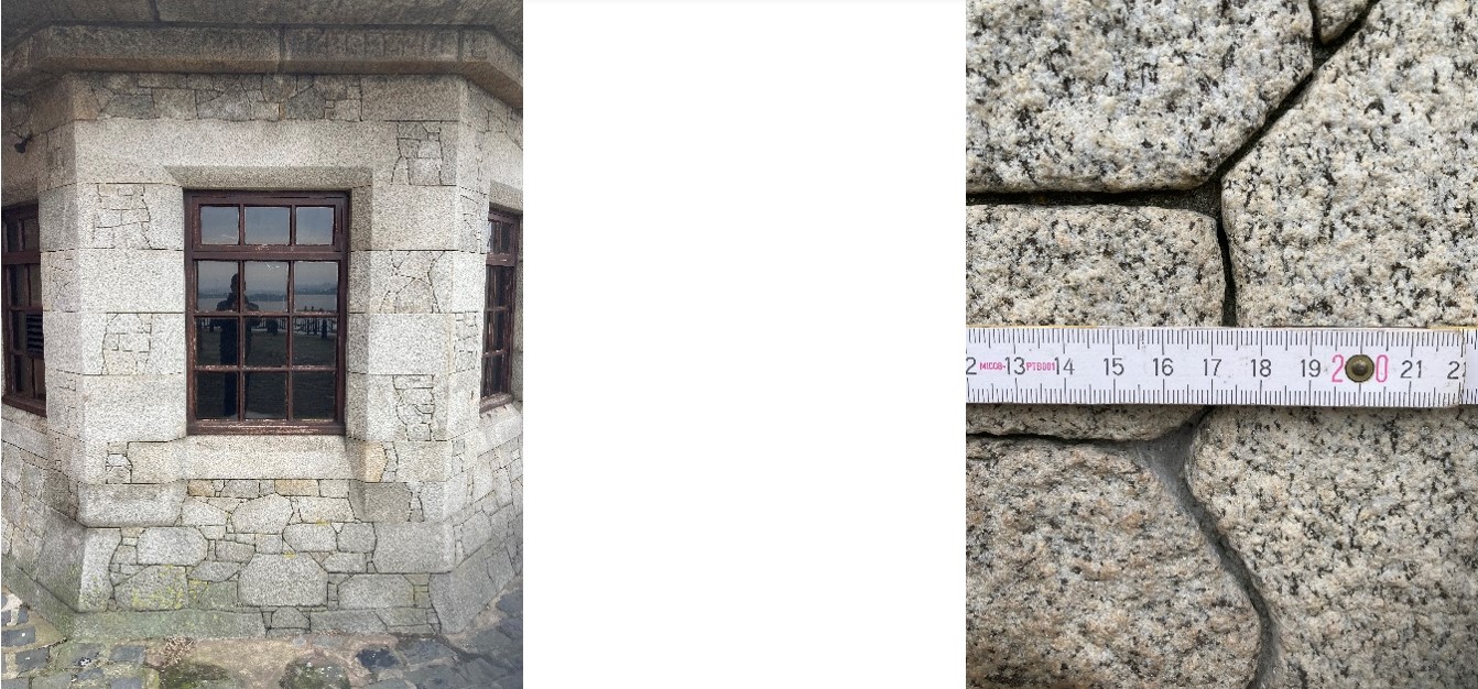 Photos 2 & 3: The fine-jointed granite construction. (Jan. 2023)
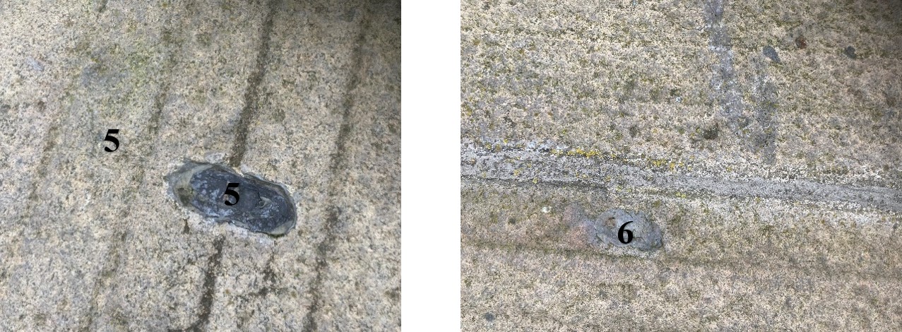
 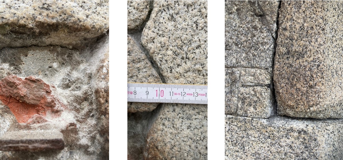 Photos 4-6: Location of samples 1, 2 and 3 together, and 4 (Jan. 2023)
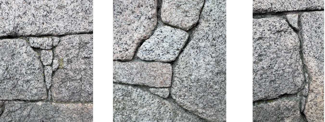 Photos 6i-6iii. Small granite pinning stones are essential to the stone hut's appearance.
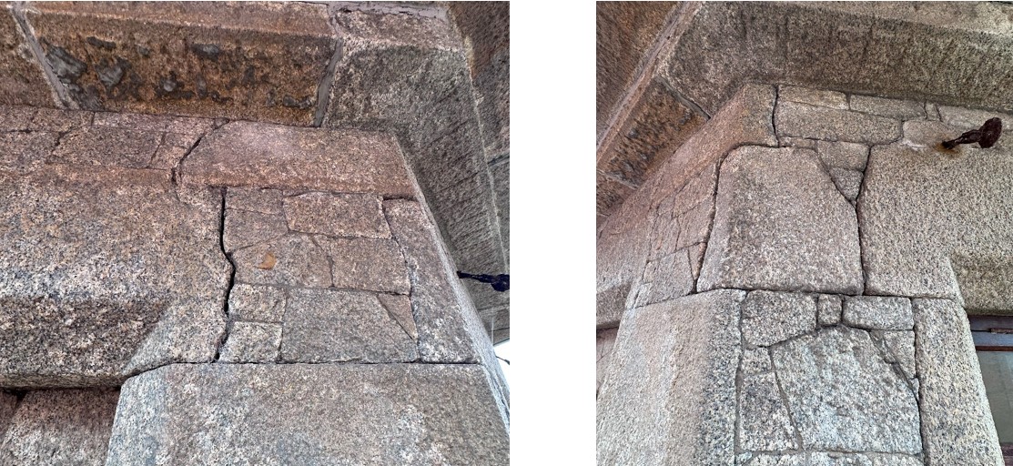 Photos 6iv & 6v (Aug. 24). On the corner nearest the internal chimney flue, where elevations WG.04 & WG.05 meet, the bedding mortar may have deteriorated and require deep pointing or localised grouting repairs.
The mortar analysis results are detailed in Appendix 1. The first sample, photo 4, from above the more recently inserted iron bar to the left of the door, appears to date from after OPC was produced commercially and may date to the later third of the 19th century. Samples 2 and 3, photo 5, were identical, and 4, photo 6, was similar to 2 and 3. It is unsurprising to find early Roman cement used as the main binder of these three samples on a building dating to 1844. Picton describes how Roman cement was first used in Liverpool as an external coating for the front of buildings in about 1820.[1] Liverpool Corporation used it on their buildings between 1832 & 1834,[2] and two Roman Cement dealers in Liverpool are listed in Gore’s Directory from 1834.[3] This natural cement appears to have arrived by ship at the port and other ports on this coast.[4] The author has encountered other examples of its use in Liverpool up to the 1870’s.
Proposed mix for repointing:
To try and recreate a similar strength mix, it is proposed to use a repointing mix of ½ parts of Ionic NHL 3.5 Old White to ½ parts of prompt cement to 1 ½ parts fine silica sand to ¼ parts PFA and ¼ parts brick dust. Some tempo (citric acid) retarders will also need to be used to provide sufficient working time, but the mix should be carefully measured out each time in small quantities that should be fully used after 20 minutes. A little linseed oil may be added to the mix when it is challenging to point extremely fine joints. (The particle size of the sand should be no larger than one-third of the minimum joint width.)
Method statement
Care must be taken, and appropriate tools must be used to prepare this random granite ashlar walling for repointing if damage is to be avoided. Decayed mortar should be removed (‘raked out’) by carefully picking it out with a thin steel hook or by easing the redundant material using a handheld hacksaw blade inserted into the joint and gently pulled forward. It is generally not advisable to use power tools to cut out the decayed or loose mortar from the fine joints due to the risk of damage to the stone, although, when used by a highly skilled operative, good results can be achieved. Traditional hand tools such as chisels can equally cause damage as these do not provide the precision required for the fine joints in ashlar masonry. Therefore, only skilled craftsmen with experience repointing fine joints should do this work.
Open joints should be flushed out with a low-pressure jet of clean water to remove all traces of dust and debris that might prevent the new mortar from bonding with the stone and old sound mortar. Additionally, damping down the stone before application of the mortar prevents the mortar from drying too quickly. Before applying the mortar to extremely tight joints of 2 ½ mm down, it is advisable to tape over the stones’ arrises with heavy-duty sticky-backed tape or similar material to protect the adjacent stones against staining and mechanical damage during repointing. Care should be exercised in the choice of tape, as some brands can leave an adhesive residue on the stone’s surface that can be difficult to remove. Before work starts, the chosen tape should be tested discretely to determine if this will happen. Repointing mortar should not be spread over the face of ashlar masonry but should be carefully limited in its application to the thickness of the joints surrounding each block. A small quantity of natural (horse) hair can be added to the mortar before inserting this mix into the joints.
The mortar can be inserted into the narrow joints using a suitably dimensioned thin tool that easily fits into the joints, such as a 3 mm COME tuck pointer or steel blade. It is important to ensure that an adequate depth of mortar is inserted into the joint, with joints fully filled where mortar is missing. As the mortar starts to set, it should be tamped back with the tip of a bristle brush to eliminate any shrinkage cracks. Once it has firmed up sufficiently, the mortar surface can be lightly scraped with a small wooden spatula or similar instrument. Where protective tape has been used, this should only be removed once the mortar is sufficiently dry but before it becomes hard; this allows any disruption to the mortar caused by removing the tape to be easily pressed back into place.
On the corner nearest the internal chimney flue, where elevations WG.04 and WG.05 meet (see photos 6iv and 6v), the bedding mortar may have deteriorated and require deep pointing or localised grouting repairs. This will be difficult due to the tightness of the joints, and smaller stones may need to be removed to grout any voids that have developed behind the walls facing stones. The grout should consist of Ionic Old White with 1 % casein (by weight) or a super plasticiser to reduce the required water content and increase flow. The grout can find its way by gravity into the voids if a clay cup reservoir is created adjacent to the access hole.
Care should be taken to avoid spilling new mortar onto the underlying stone faces. This can cause staining that is difficult to remove. Permanent staining is less likely if the mortar is of the right consistency and the stone surfaces are dampened before the work starts. Any accidental spillage or smearing should be washed off immediately with a fine jet of clean water, but this could be avoided in the first place by setting some temporary protection in place below the work area to contain any spillages.
It should be noted that the larger granite stones have small pinning stones placed between them (see photos 6i to 6iii) to continue the ashlar effect, increase the detail within the walls, and reduce the damaging impact that big stones alone would have on the scale of this small structure. These pinning stones must be reinserted if disturbed during the raking-out process.
Removal of existing mastic from upper roof sections, existing cement repairs to previous lifting points, re-pointing, removal of existing mastic and foams and pointing to lower outer slabs, and re-pointing work.
The results of our August 2024 inspection are shown in diagram 1. The upper part of the roof comprises two slabs surmounted by what may be a later stone bulb finial that perhaps replaced a stone chimney visible on the adjacent ‘hut’ (see photo 1). Photos 47 and 48 show evidence of a fireplace and chimney flue, and illustrations Nos. ii & iii show that the Hartley Huts were first conceived as having a fire hearth.
The central southern slab is badly cracked, albeit with very fine hairline cracks, which may be associated with structural settlement or movement of the building that is close to large movements in water pressure from the tidal Mersey. Most of the cracks have been covered by mastic, but some appear newer; see crack numbers 7i, 7ii and 3 shown on the diagram and photos 8 and 9. It is suggested that a grid is laid out over the slabs and the cracks mapped accurately and monitored accurately for the next few years to ensure they are not worsening (M Womersleys can provide this service if required).
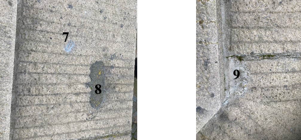
Other distress can be found in the outer slabs, again on the southern half of the building, where previous lifting points, shown as dark blue ovals on diagram 1, have been inappropriately filled with foam, mastic (see Photos 15iii-15vii) or cement mortar that has concentrated decay in the granite surface, see reference numbers 8 and 10/11, as shown on photos 13 and 15. There are also two previously cement-repaired areas to tackle the delamination on the granite surface; see references 9 and 12, shown in photos 14 and 16. Since the last inspection of the slabs in January 2023, the weather has lifted the cement mortar infill to areas 11 and 12. It must be removed and resurfaced with more sympathetic hydraulic lime and Roman Cement Stucco-based stone repair materials. (High-fat lime mortars will damage the silica-rich granite and cause it to suffer excessively from the weather.)
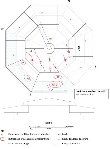
Diagram 1: Distress in the Granite Slab Roof
The wetness and staining around the joints within the outer slabs suggest they have been allowing water to penetrate the building. The current pointing should be carefully removed, except where it is very dense and cement-based and cannot be removed without causing severe damage to the surrounding granite blocks and pointed up with a mortar mix comprising of 1 part prompt cement to 1 part Leighton Buzzard to 1 part fine silica sand to a depth of 20 mm from the upper, lower and edge surfaces of the slabs and the remaining space infilled with bentonite clay powder compacted within the space, see Diagram 2 below. It should be noted that the pointing alone will not stop water penetration as the pitch of the stone slabs is too low to prevent wind-driven rain from being forced under the upper slabs into the internal ceiling space, see photos 19 and 20. It is still being determined how wide the gaps are between the slabs to determine if the suggested use of bentonite will be possible; this work will have to be adapted on-site as required.
In addition, the pointing between the upper and lower slabs in the south and southwest part of the roof has also cracked above and below, see photos 17, 18, 21 and 22 and diagram 1, and is failing, perhaps due to the same structural movement mentioned above. After it is pointed, this area should also be monitored for further cracking, together with the rest of the roofing slabs. It should be pointed up with a mortar mix comprising of 1 part prompt cement to 1 part Leighton Buzzard to 1 part fine silica sand to a depth of 25 mm (some tempo retarder will be required)
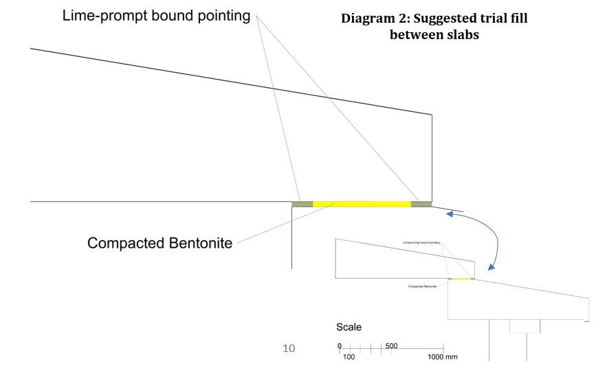
Diagram 2: Suggested trial fill between slabs
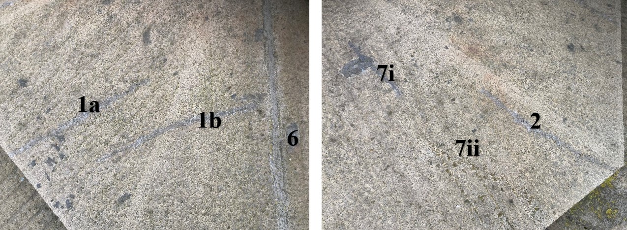 Photos 7 & 8 (Jan. 2023)
  Photos 9 & 10 (Jan. 2023)
 Photos 11 & 12 (Jan. 2023)
  Photos 13 & 14 (Jan. 2023)
 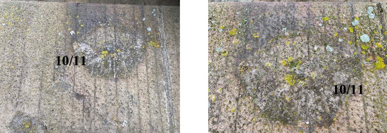 Photos 15i (Jan. 2023) & 15ii (Aug. 2024)
 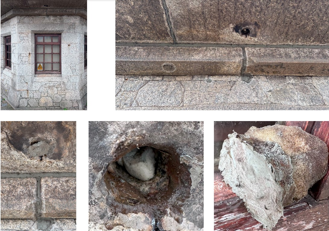 Photos 15iii-15vii (Aug. 2024). Using water-retaining foam fillers and mastics to fill the previous lifting point holes has caused severe damage to the surrounding granite, including delamination, cracking, and staining.
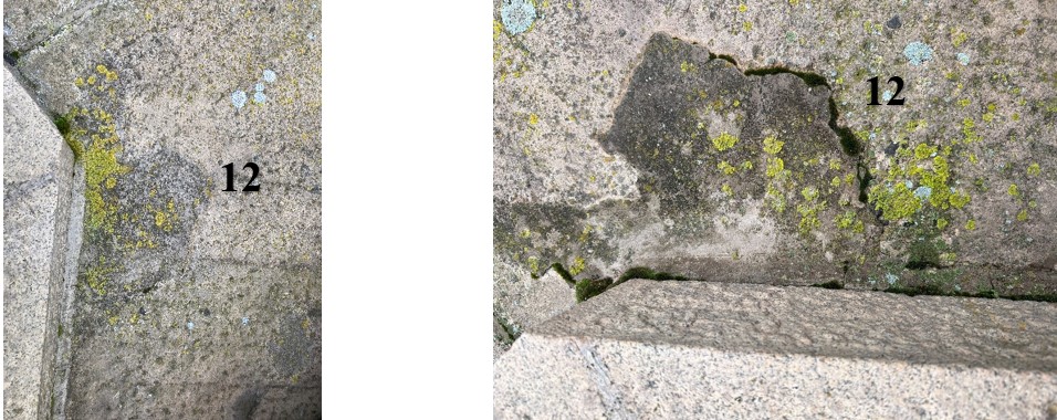 Photos 16i (Jan. 2023) & 16ii (Aug. 2024). Delaminating and failing cement-based stone repairs.
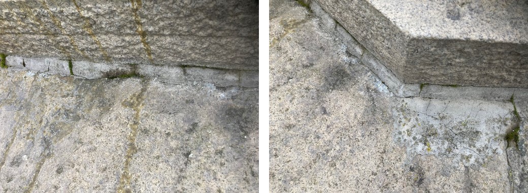 Photos 17 & 18 (Jan. 2023). Failed cement pointing requires removal and the insertion of bentonite behind new pointing if sufficient depth (greater than 70 mm overlap exists between the upper and lower stones).
  Photos 19i & 19ii: Water penetrating below the slabs. (Jan. 2023)
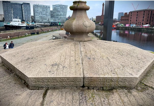
Photo 20 (Aug. 2024): the upper capping slabs' right-hand half has microcracks throughout; see Diagram 1.
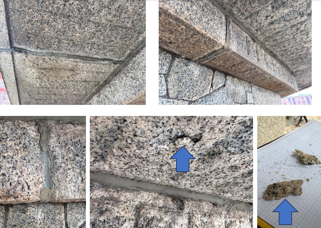 Photos 20i-20v. Mastic-covered joints, some with dense mortar behind, cause excessive water to be trapped in the granite, the surface of which is now loose under the soffits. (Aug. 2024).
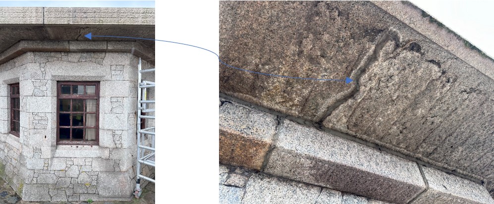 Photos 21 & 22 (Aug. 2024): Filling over structural cracking with modern mastic has exaggerated the decay of the adjacent stonework, causing delamination to the underside of the granite slabs.
The mastic applied to the joints on the underside of the projecting roof slabs could trap water in the granite; see photos 15iii-15vii, 21, 22, and 39 to 41. It is likely to have been applied to avoid cracking in mortar joints. However, medium-strength mortar and granite have a similar Coefficient of Expansion. When the building materials change in dimension in response to temperature changes, the mortar should not exhibit excessive cracking as long as any repointing goes back at least 25 mm into the joint. In line with our mortar analysis results, we would suggest that this building's vertical elevations, where required, including these areas below the roof overhang, which have previously had modern polysulphide mastic applied, should be repointed with ½ part Ionic NHL 3.5 Old White to ½ part prompt cement to 1 ½ parts fine silica sand to ¼ part PFA and ¼ part brick dust. However, it should be noted that if there is structural movement in the whole hut, the mortar may well crack again, which will require monitoring.
At this stage, it is not proposed to tie the roof slabs together as they need to move independently during heating and cooling.
Removal of vegetation and greening to external stonework faces
There has been a request to remove green organic growth from the stone to the right of the door; see photos 21i and 21ii. Using any solvent-borne biocides or hydrofluoric-based acids on this wall would be inappropriate, as they would dissolve the silica in the granite. However, diluted hydrochloric acid thoroughly washed off the wall could be used, followed by applying Beeck Fungicide.
Method statement for using BEECK FUNGICIDE.
· Check effectiveness by making samples.
· BEECK FUNGICIDE is a ready-to-use product. Apply to saturation to the prepared surface using the flow coating technique. Thoroughly remove using hot water after a minimum exposure time of 24 hours by a medium-pressure water jet.
· To increase the long-term effect, apply the FUNGICIDE to the cleaned surface without subsequent rinsing.
· Minimum temperature: +5°C. Please do not use it on heated surfaces during hot weather.
· Observe Safety Instructions on safety data sheets
· Ensure proper ventilation while processing and keep away from any ignition source.
· Clean appliances, tools and clothes with plenty of water immediately after use.
Photos 22i & 22ii: Limited organic growth at lower levels to the right of the door, near the gully drain. (Jan. 2023)
Removal of rust staining to stonework and more modern steel bar.
There are iron fixings or embedded ironwork in all but one of the elevations, shown on Diagram ‘i’ and photos 23-36 below. Three cut-off lengths of flat bars can be found to the left of the door opening. Other, now cut-back ironwork appears to have provided security or protection to some of the windows, as on elevation WG.03, see photos 29 and 30, and other pieces of iron include a bolt, elevation WG.07, photos 37 and 38, and hooks and hangers, as seen on elevations WG.05 & WG.06, photos 32 to 35.
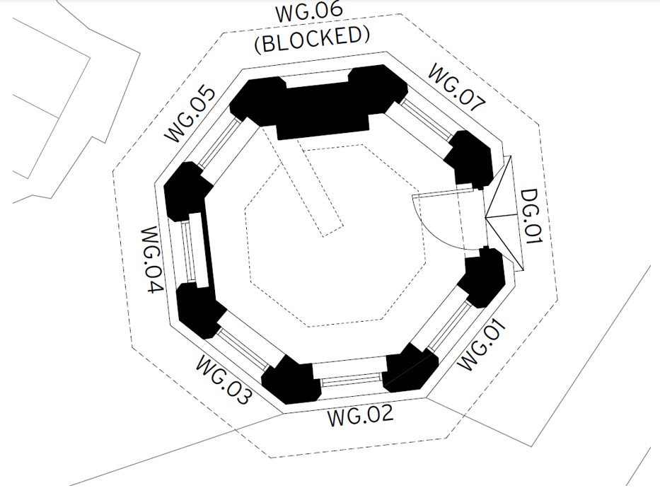
Diagram i: The eight referenced elevations of Hartley Hut (in the plan by Harrison Stringfellow).
Unusually, except for the more modern steel to the left of the doorway, none of the iron appears to be expanding excessively as it rusts and does not appear to be causing any damage to the stone. This is because it is mainly wrought iron, which remained dominant for structural applications until the 1880s. Wrought iron is an iron alloy with a shallow carbon content, unlike cast iron. It is a semi-fused mass of iron with fibrous slag inclusions (up to 2% by weight), which means it is tough, malleable, ductile, and, in this case, especially, corrosion resistant. The silicate filaments in the slag protect the iron from corrosion.
It is understood that there is a desire to keep all of the ironwork remains, which helps tell the history of this workman’s ‘hut’, and trying to remove them may cause damage to the stonework. However, the three more modern insertions to the left of the door, which are cracking the adjacent stone, see photos 25i 25iv need to be removed.
The rust stains can be removed using diluted hydrochloric acid, which does not react with granite or excessively with the old Roman cement-based mortar; see the analysis results in Appendix 1. The rust, Ferric Oxide, reacts with Hydrochloric acid and gives Ferric Chloride and water. Ferric Chloride is soluble in water and should be cleaned off with copious amounts. The walls must be scrubbed with water to remove all precipitating and potential chloride salts from the stone surfaces as part of the cleaning operation. M Womersleys undertook a small trial, as illustrated by photos 37 and 38, which showed that multiple applications of this acid would remove most of the iron staining.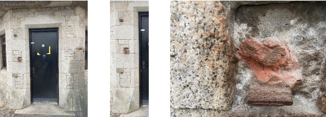 Photos 23-25: DG.01 with three pieces of flat bar to the left of the door, with a close-up of the central fixing. (Jan. 2023)
 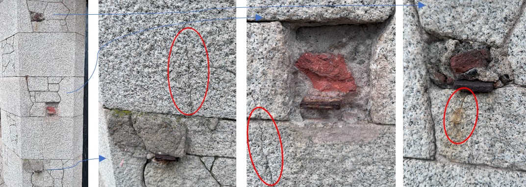 Photos 25i-25iv (Aug. 2024): Damage is caused to the adjacent granite stones by the more recent flat steel bars expanding as they rust.
 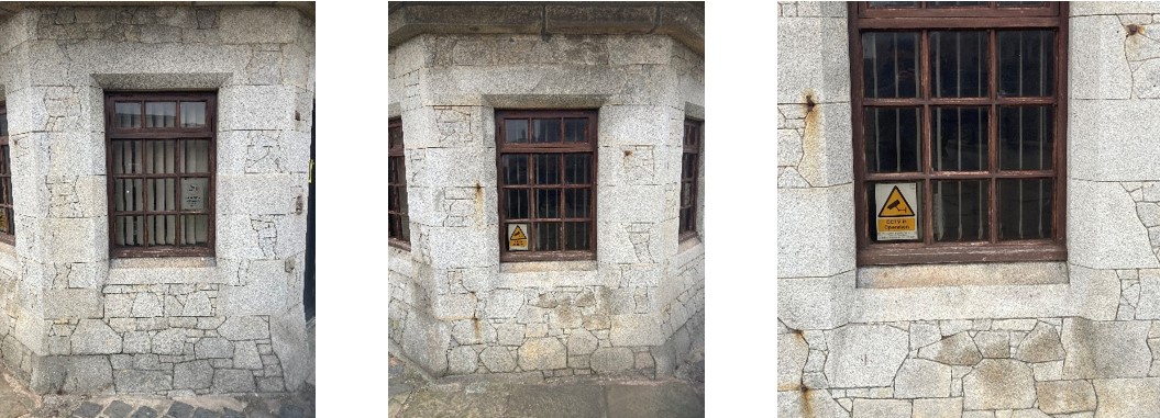 Photos 26-28 (Jan. 2023): WG.01, WG.02 and a close-up of WG.02
 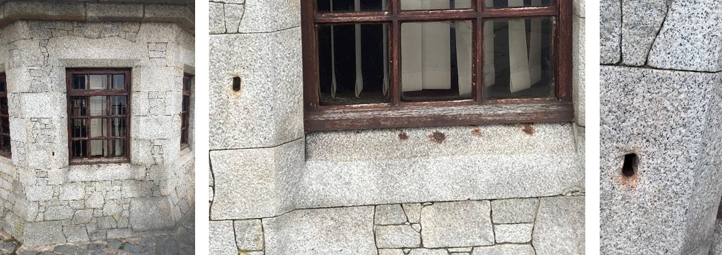 Photos 29, 30i(Jan. 23) &30ii (Aug 24): WG.03 with ironwork in the sill and jamb. Leave the whole in the jamb unfilled to avoid trapping further expansion of the remaining iron.
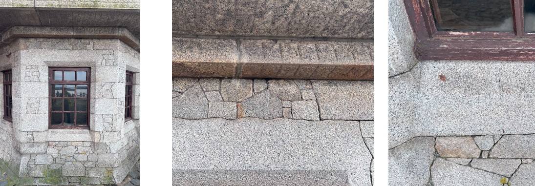 Photo 31i-31iii (Aug. 2024): Location of rust spots on elevation WG.04
 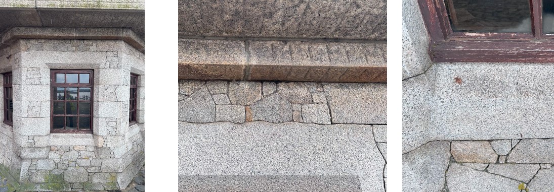 Photos 31-33: WG.04, WG.05 and a close-up of the iron on elevation WG.05 (Jan. 2023)
 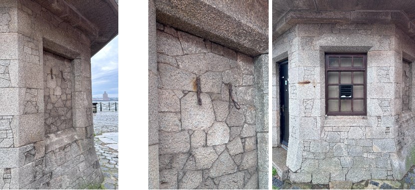 Photos 34, 35 & 36 (Aug. 2024): Elevation WG.06 and a close-up of old iron hangers and elevation WG.07.
 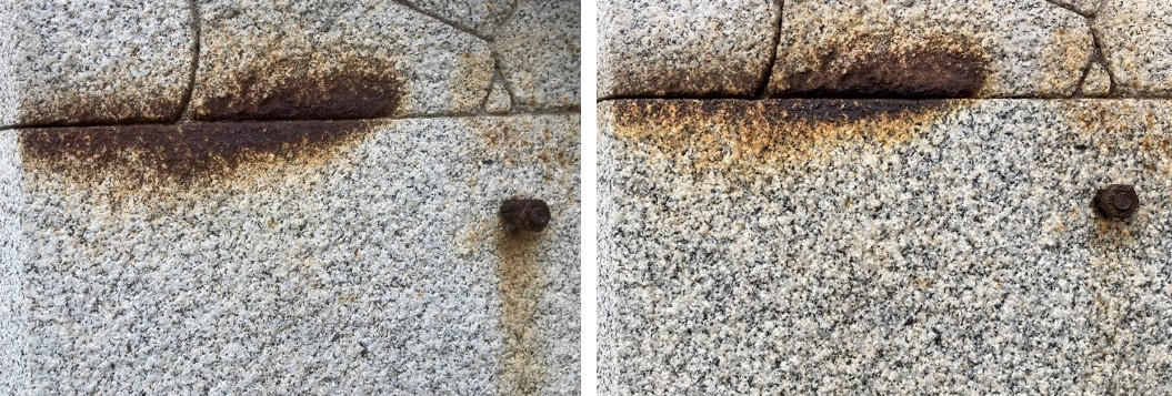 Photos 37 & 38: WG.07: Before and after an initial clean, below the joint line, with 10% hydrochloric acid in water. (Jan. 2023)
 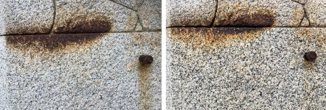 Photo 38i (Aug. 2024). Minimal new rust staining 18 months after cleaning.
Once the flat bar has been removed from the left of the door, new pieces of matching granite at least 40 mm in thickness need to be indented into the gaps left with tight joints and using the same pointing mix specified above for the general repointing work.
Remove existing paint from internal walls.
Old buildings need to allow for moisture exchange, internally and externally. Using plastic, acrylic-based paints has exacerbated damp problems and excessive efflorescence in the internal surfaces of the bricks and granite blocks within the Hartley Hut. These paints hold moisture in the surface and prevent it from naturally evaporating. The damage caused by modern paints is very visible in Photos 52 to 59.
The best way to remove paint without damaging the stone is to apply chemical (alkaline) softeners and then go over the surface with a DOFF stone cleaning system, which uses high-pressure water heated to 150 degrees. This removes all traces of paint and, if done with care, leaves the stone unscathed. However, this procedure can nebulise damaging lead found in the paints within the hut and damage the health of operatives. Lead cannot be put in the atmosphere within the confined exposure space of the hut. Aggressive techniques such as nitromors paint stripper, sandblasting, and a heat gun with scrapers should not be used as they will most likely cause irreversible damage to weakened brick surfaces.
Poultice-type paint removers such as ‘Peelaway’ or ‘Kling Strip’ are recommended for the internal walls in the small, confined space of the hut. The methodology to be followed is set out below:
· In each area where work is to be done, thick plastic (protection board) needs to be used on the floor and other surrounding surfaces for protection. Secure it using duct tape and weight to keep it in place, e.g., sandbags.
· Ensure all power has been isolated and nothing is live in the hut.
· All the redundant electrical equipment, cables, alarm systems, and conduits must be removed from the hut to carry out the paint stripping. These are shown in photos 69 to 74.
· All workers using and working around PEEL AWAY or similar products must wear protective clothing that completely covers their skin.
· Always have “Barrier Cream” on-site and rub on hands before commencement
· Use gloves with excellent liquid run-off, abrasive, and chemical resistance. These gloves are suitable for laboratory work, manufacturing, and solvent handling.
· Use chemical-resistant safety boots always.
· Use an appropriate filter face respirator mask.
· Always use Chemical & Impact goggles for eye protection.
PEEL AWAY/KLING STRIP APPLICATION
· The application must be per the manufacturer’s instructions.
· Apply the product with a trowel at a minimum of 3 to 4 mm thick.
· The product is then covered with a special cover, paper sheet and sealed with masking tape.
· The time needed for the Product to be left on will vary according to test sample results. The product dwell time can vary for different substrates, number of layers and surfaces.
· Carefully remove all loose coatings, fully contain all solid waste in thick heavy duty tie-up bags, and store safely, ready for disposal.
· Thoroughly wash down the surface with only a light pressure cleaner to remove residue, as the product will do most of the stripping work. High-power pressure cleaners are not recommended as they can damage substrates and nebulise lead.
· Vacuum up water with Aqua-Vac machines. Aqua vacuum machines can collect wastewater and contain it for later disposal. Once wastewater has been removed, settled particles can be disposed of as solid waste.
· All surfaces are to be left completely dry and checked for complete removal.
· All surfaces must be neutralised.
· Consideration must be given to water disposal and runoff into the adjacent docks.
· Sandbags should be used as a filter for run-off water during washing down.
· Recover any contaminated water, filter and treat it appropriately.
· Remove non-usable solid material for disposal in an approved facility.
The ceiling, being granite slabs and having a deep pitted texture, may be difficult to clean using the poultice system alone, and if this can be combined with the use of the Doff system where the operatives are located OUTSIDE the building using a long lance through heavy-duty plastic sheeting over the door entrance. The following safety methods will need to be followed as set out below:
· Only use the equipment for the recommended times.
· Equipment must not be left unattended and locked in a secure container at the end of each day or taken home.
· Always check all leads and equipment before use for signs of wear and tear.
Do not use any equipment if found to be even slightly damaged.
· All other personnel except the operator are to be kept away from the working area
Operative PPE must be worn: rubber-dipped cloth gloves, eye protection (visor), ear defenders (above 30 bar pressure), and waterproof clothing (skin to be covered).
· 110v to be used.
· The building surface will be cleaned by a capable operator who has been instructed to use the DOFF Cleaning System correctly.
· The DOFF will be connected to the water supply and switched on.
· Care to be taken when handling the lance as some parts can become very hot.
· Adjustments of the water volume, pressure and temperature controls should be made whilst maintaining an appropriate distance of the nozzle from the work.
· A balance should be achieved to obtain an effective cleaning result without abrading the substrate. Different nozzle specifications, such as aperture and spray angle, may also be considered.
· Equipment should be placed in a well-ventilated area out of the reach of the lance or other water spray.
· The power supply to the DOFF is provided by a 110v. The cable is to be fully checked for signs of wear and tear before each use, and if any faults are found, it must not be used until a replacement is provided.
· The normal fuel for the DOFF is light (35 seconds) gas oil (red diesel), or motor vehicle diesel (white) fuel or domestic central heating oil. The latter will not be suitable for diesel compressors, etc. This will be stored in suitable marked containers or drums away from heat or direct sunlight. Storage will generally be at least 10 metres from the DOFF heater unit.
· The ideal location for the DOFF is in any open-air position, so fumes can be released into the atmosphere. For this contract, the DOFF will be situated on the ground.
· At the end of the working day, dirt particles, etc., are placed into bags and stored safely for appropriate disposal.
Removal of Salts from the interior surfaces
The internal walls of the stone hut are contaminated with sulphate salts, perhaps from the ground below, the construction mortars or the bricks, or previous storage uses within the building; see photos 42-45 below. In addition, there is salt contamination internally and in the building mortars around the former chimney flue and fireplace; see photos 46-49. These salts can only be tackled once the dampness rising in the walls is reduced by improving drainage around it. Installing a foamed glass subbase below the floor would help, but it would need to be linked effectively to cleared-out drains, or it may not drain away, depending upon the nature of the made-up ground below. (Although because of the battered base to the outside walls, water ingress cannot be reduced entirely.) Once the level of dampness has been reduced, the salts need to be removed. This can be done with three coats of clay poultice, left to dry completely before removing and reapplying a fresh clay poultice. 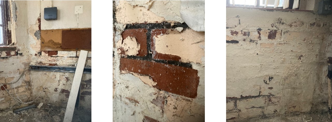 Photos 42-44: Salt damaged paint on the dense inner brickwork. (Jan. 2023)
 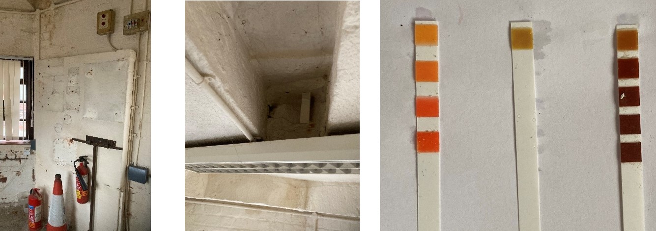 Photos 47-49: The set forward brickwork identifying the location of the former fireplace, the flue area above and to the left, and tests that also showed sulphate salt concentrations of over 800 mg/l, but no nitrate or chloride salts. (Jan. 2023)
 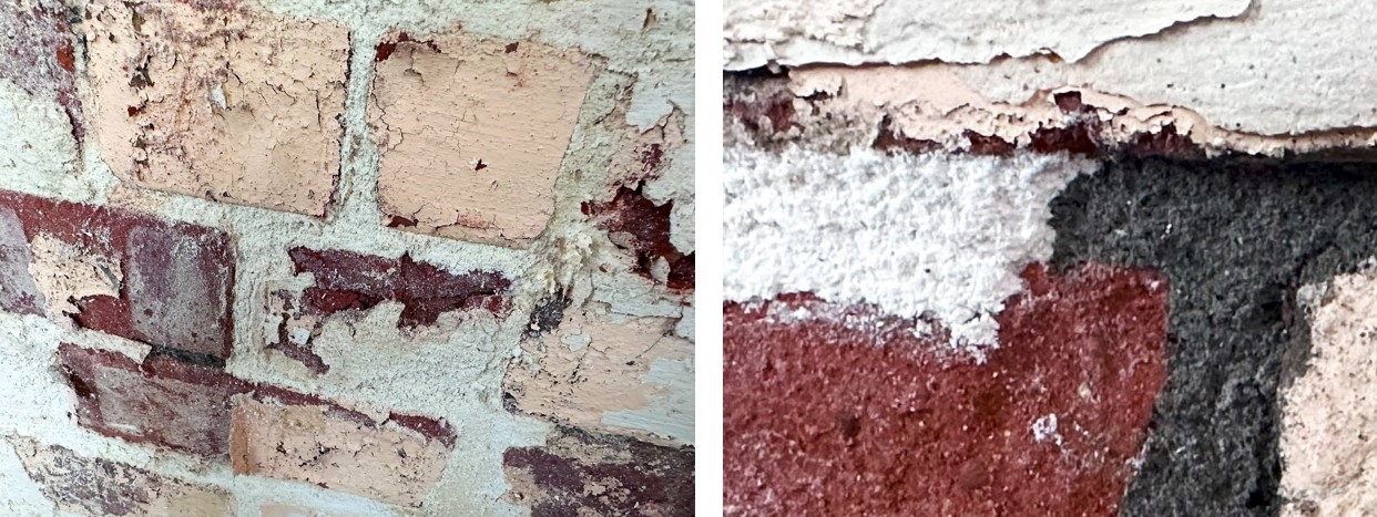 Photos 50 & 51(Aug. 24): Continued efflorescence, especially between the brickwork joints and behind oil and acrylic paint build-ups.
 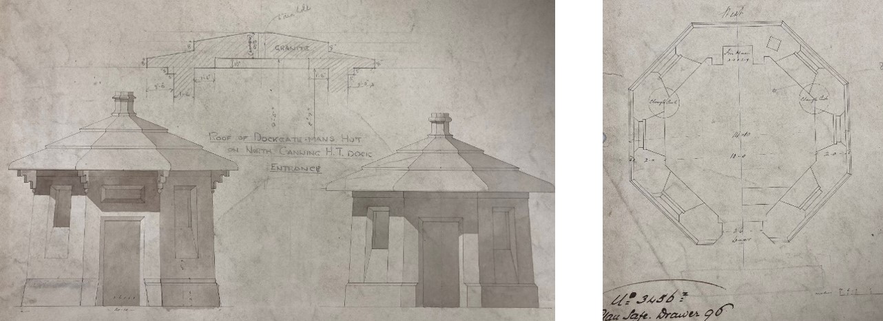 Illustrations ii & iii: Jess Hartley’s drawings for the Hartley Huts show the proposed fireplace and chimney.
 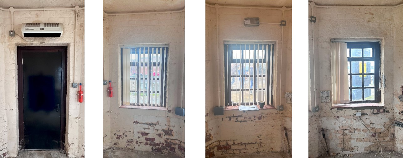 DG01.(Aug.24) WG01. (Aug.24) WG02. (Aug.24) WG03. (Aug.24)
 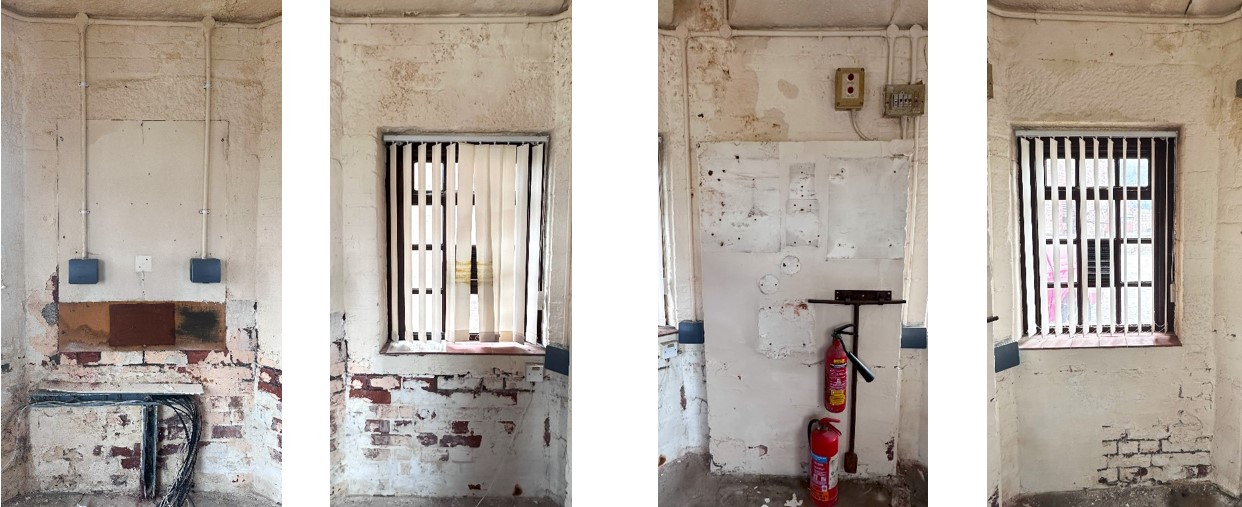 WG04. (Aug.24) WG05. (Aug.24) WG06. (Aug.24) WG07. (Aug.24)
Photos 52-59: The internal wall elevations at Hartley Hut
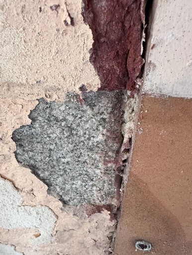
Photo 60 (Aug.24). Behind the existing paint are sound and salt-damaged bricks stabilised by granite quoin stones and granite heads above windows. 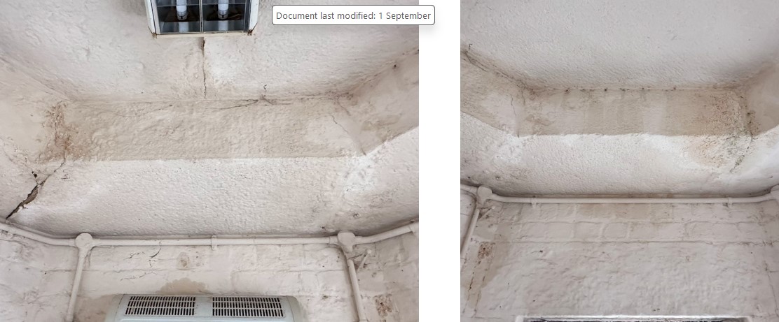 DG01.(Aug.24) WG01. (Aug.24)
Photos 61-62: The internal visible lower slab sections at Hartley Hut
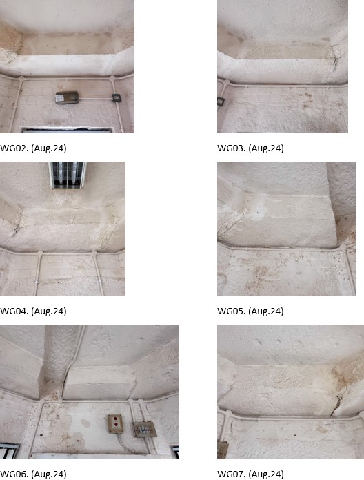
Photos 63 & 68: The internal visible lower slab sections at Hartley Hut
Works required after paint stripping
Photos 61 to 68 show the distress behind the paint finishes on the lower roof slabs and how joints between them have opened in the past and been filled. Once paint stripping is complete in this area; a repair schedule will be prepared for the necessary structural repairs and removal of inappropriate filling materials.
Specification for further investigatory work required for the existing fireplace, windowsills, and floor screed.
Together with poor drainage around the outside of the building and potentially below the floor, the modern concrete floor screed is trapping water and contributing towards forcing water into the external walls, which in turn is exacerbating the salt efflorescence in the brickwork and the mortar joints. As part of the first phase of work, the screed, photos 70 & 76, needs to be removed over an area of 600 x 600 mm to determine what is below and decide on the future of the floor. In addition, the concrete infill that makes up the base of the modern tiled windowsills, see photo 75, also needs to be removed below one window to allow a decision to be made as to whether the exposed bricks are suitable as a sill and to allow the replaced windows to be ordered to the correct size.
Similarly, to allow consideration of reinstating the fireplace, the modern paint will be stripped off the fireplace beyond the height of the fireplace head. 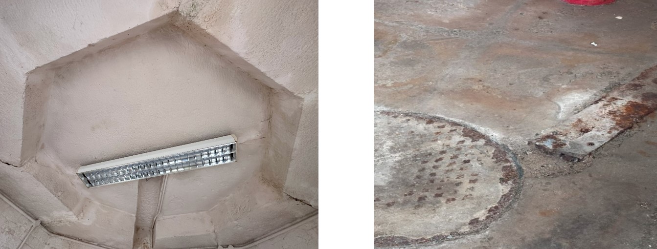 Photos 69 & 70 (Aug 24). Remove all light fittings and conduits.
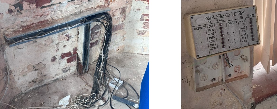 Photos 71 & 72 (Aug 24). Remove all telephone and security apparatus and gables.
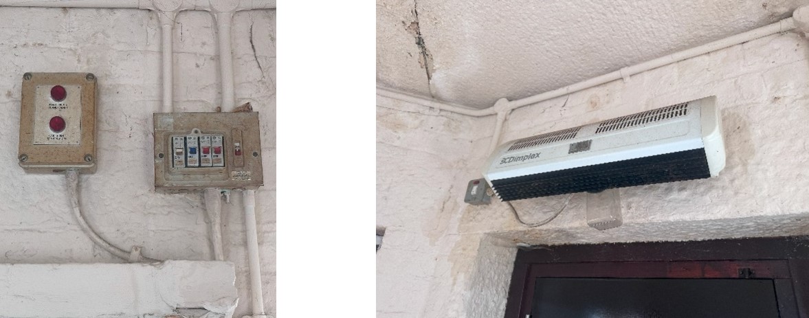 Photos 73 & 74 (Aug. 24): After isolating the power supplies to the hut, remove fuse boards, switches, and heaters.
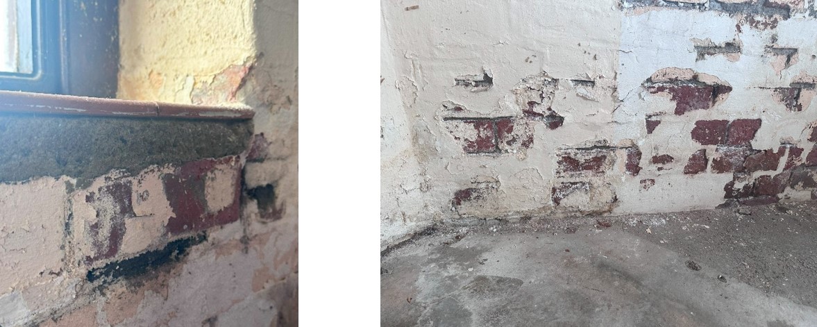 Photos 75 & 76 (Aug. 24). Undertake further investigatory work by removing a later concrete infill above the sills of the more modern windows and the concrete screed to the original floor level.
Bibliography
‘Gore’s Directory of Liverpool and Its Environs for the Year’. Gore’s Directory Liverpool, 1834.
J. and J. Mawdsley. ‘The Account of the Corporation of Liverpool, with Their Treasurer from the 18th of October, 1832 (to the 31st of August, 1834).’ Liverpool Corporation, 1834.
Sir James Allanson PICTON. ‘The Architectural History of Liverpool ... Papers Read Before the Liverpool Architectural and Archæological Society’. The Liverpool Architectural and Archæological Society, 1858.
[1] Sir James Allanson PICTON, ‘The Architectural History of Liverpool ... Papers Read Before the Liverpool Architectural and Archaeological Society’ (The Liverpool Architectural and Archaeological Society, 1858), 61.
[2] J. and J. Mawdsley, ‘The Account of the Corporation of Liverpool, with Their Treasurer from the 18th of October 1832 (to the 31st of August 1834).’ (Liverpool Corporation, 1834).
[3] ‘Gore’s Directory of Liverpool and Its Environs for the Year’ (Gore’s Directory Liverpool, 1834).
[4] This use certainly extended to Lancaster in the same period, based on render analysis by the author at Lancaster Grand Theatre. In addition, samples taken by the author at the Customs House, Fleetwood, also confirmed the use of early cement mortars further up the coast in 1838. Charlie MacKeith checked the schedule of duty rates of duty for all goods entering and leaving the port of Fleetwood rates of duty for all goods entering and leaving the port of Fleetwood, (appended to the act of parliament for the port in 1837), which lists cement. This can only refer to Roman cement as OPC had not been produced at this early date.
Related Articles

Guidance Sheet for burning lime, quenching, slaking and using lime for conservation work in Antigua
M Womersleys Ltd assisted the Harrison Centre to allow them to construct an active lime kiln in their…
The steps members of the Waterton’s Wall restoration team, with support from Mark Womersley, have been following to consolidate, conserve and repair this historic wall that represents the successful efforts of Charles Waterton to preserve the wildlife that lived on his estate near Wakefield in West Yorkshire.
1. Fill deep voids behind the wall’s facing stones with deep pointing work. The works involve …
Mark spent a day recording a historic timber-framed garden building at Woodsome Hall
Mark Womersley, as part of his voluntary work with the Yorkshire Vernacular Buildings Study Group, spent…